
We’ve all been there. Tooling down the road, motor purring, all is well, then “cough-sputter –sputter- cough”. You frantically move the selector lever to the second tank and another “cough-sputter-sputter-cough-lurch” . Then nothing. You either haven’t been minding the gas gauge, it’s inaccurate, you’re already drawing on the reserve tank, or perhaps you’re in a Swiss model 404, or the lever is a PITB to rotate. Whatever. Out you climb, spare gas into the forward tank; that tricky registration of the lever in the “you hope it works” position, then you either proceed to drain you battery by cranking, and hoping, or you proceed to actuate the mechanical pump priming lever with the expectation that you will get a charged float bowl in the process.
One of the joys of 404 ownership, especially with only the mechanical pump installed, is the first time (or two) you have the aforementioned experience. While we can’t offer any solution to fuel level inattention, we can offer a fix for that selector valve that caused you a weak battery, burnt fingers on a hot motor, frustration in lever placement, or an errant trip schedule.
That selector, like the rest of your truck, is perhaps 50 years old now. If you’ve had this experience, it’s time to consider carrying a spare, or more economically, rebuilding yours. They are actually quite simple affairs. Here’s a how-to DIY for a functional fix.
As a point of reference, move the lever counterclockwise until it stops. This should be the OFF position. Remove the three fuel lines and then remove the valve from below with the lever installed.
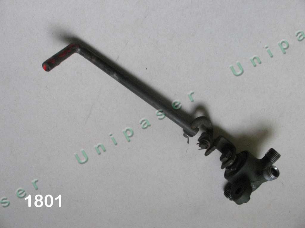
Note the position of the lever and its connecting link for reference on reinstallation.
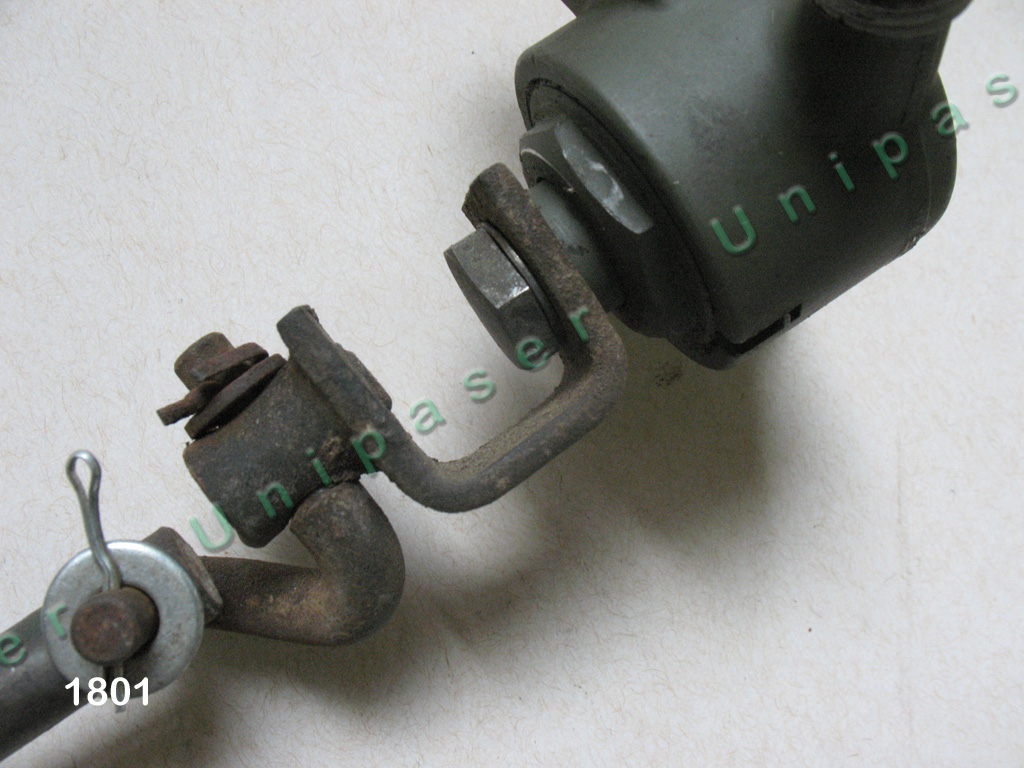
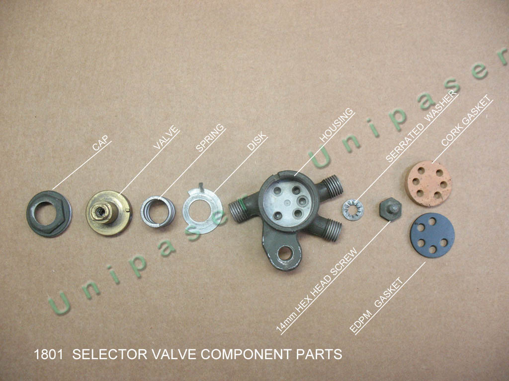
Remove the 14mm hex screw and remove the link and handle. Note the shoulder the U-shaped bracket rides on.
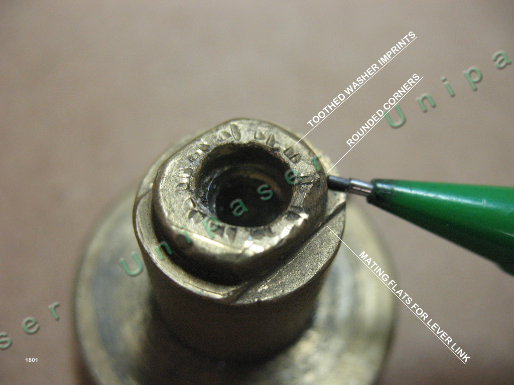
These often become rounded with age and while not prohibitive, a good solid fit should be sought prior to reinstallation.
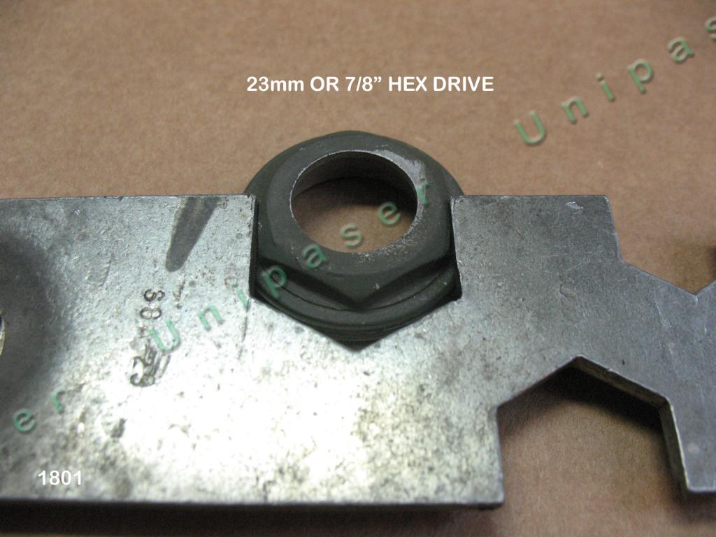
Remove the cap screw and serrated washer. It is a 23mm (7/8”) hex. Any wrench will do, however we use a nice flat tool originally used on an air compressor or similar. Not only is it a perfect fit, but it aids in reassembly as you will see later. Be careful when removing this cap as it is under great spring tension and will leap up if not held in check.

Once the cap is off, you can remove the disk and valve. The disk is rather delicate in that the tab is prone to shearing off. If this happens, or has happened to you, the valve is toast and you can rotate the lever freely 360˚. The alternative here is to make another disk. Not illustrated below, but present in all valves we’ve encountered, is a anti-friction fibre shim between the valve body and below the disk. Its diameters are approximately 15 and 24mm inside and outside respetively
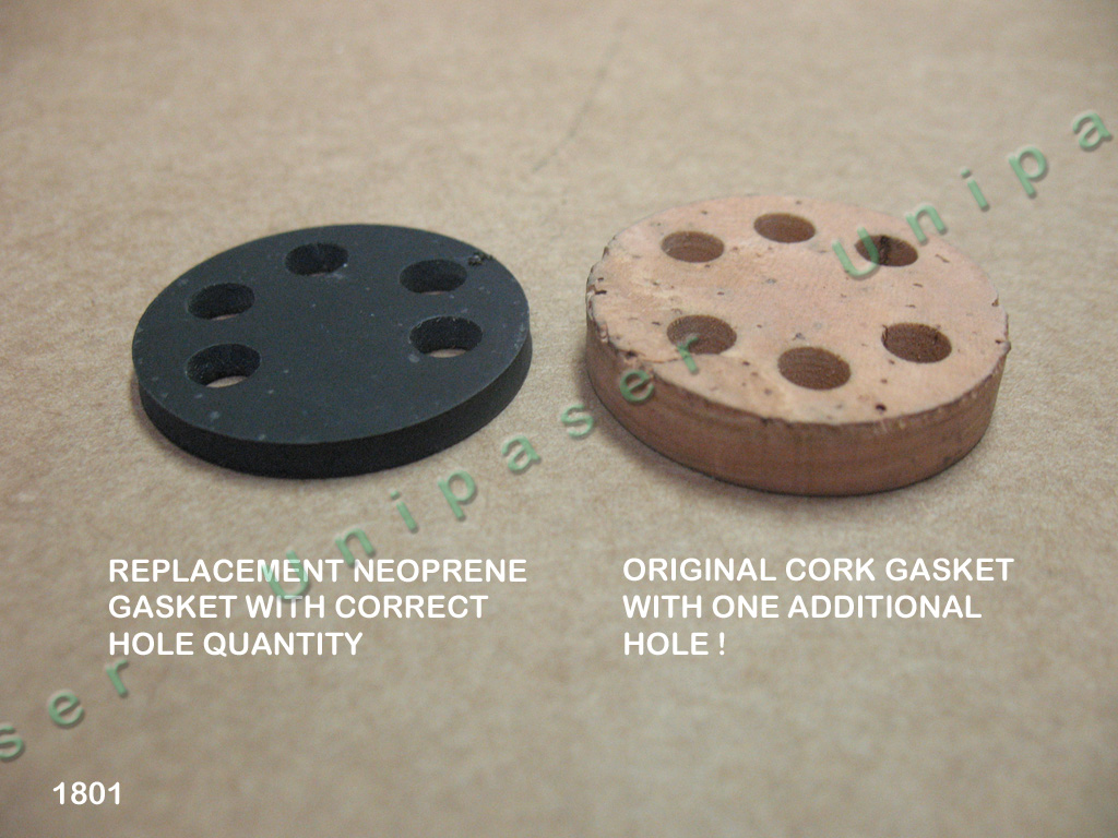
Once the valve is off, you can see what age does to the gasket underneath. Original gaskets were made of cork and are quite friable. Newer gaskets, while made of neoprene, are more durable, yet prone to rupture as well, especially if you’ve been so fortunate to come into a 404 that’s been sitting in bubba’s field for umpteen years and has dried out due to lack of fuel – despite the fact that “it was running when parked”. Cork gaskets were approx.. 6mm thick before compressing and unless soaked prior to installation can be challenging. Neoprene gaskets are typically more easily installed.
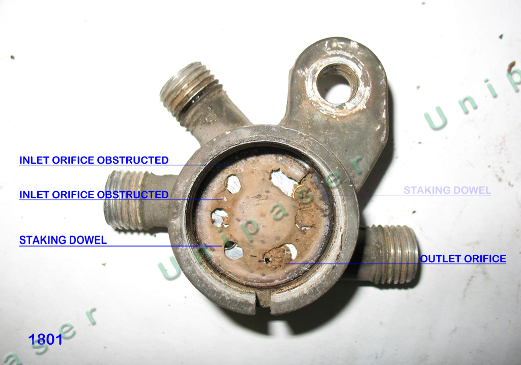
One other aspect of these valves we’ve noted over the years is that there were two versions. Older specimens we see have a pair of cast locator dowels in the floor of the housing while later models have staked brass dowels. It is not relevant as the thickness of gasket is above the height of these locator dowels so that the valve does not chafe against them. They are as well of like diameters, so that replacement gaskets have a snug fit.
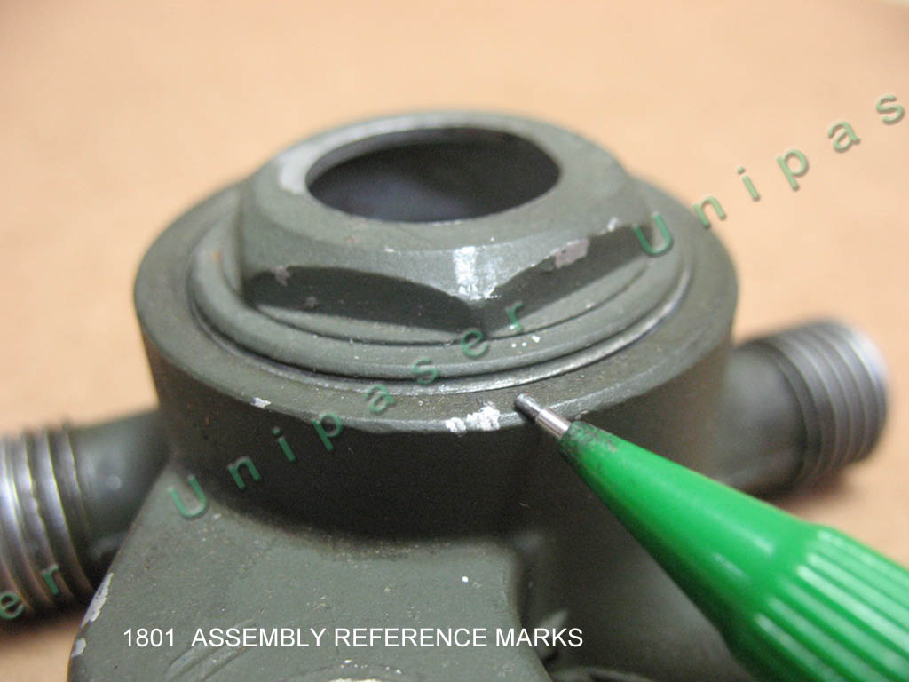
Reassembly is straightforward. Due to the stiff spring compression force required, we use this trick to aid in getting the threads correctly seated when replacing the cap. With no internal parts in place, install the cap until lightly seated. Then back out the cap slowly, under finger tension, and carefully observe one of the hex shoulders and where it aligns with the housing precisely when it is released. Mark the housing and the hex point. When all parts are in place, this we use as a start point for the pressure and rotation required on the cap.
Once all is assembled, test the function as follows:
Place a compressed air blow gun against the outlet orfice. With 5-10 lbs of air and a snug fit, slowly rotate the valve lever clockwise from the OFF position. As the valve comes to the first position you should hear air freely escaping. Continuing the rotation, you should hear, and feel air coming out of the other orifice, and none out of the previous orifice. We have also noticed that the R is marked on this second opening, which happens to be the main (rear) tank on most 404.1 vehicles. Perhaps the valve had an application on some other vehicle(s) as well ?
Should you want to test your valve prior to removal you can use this procedure as well. If there is fuel in both tanks you will hear bubbles rather than escaping air.
Should you decide to attempt a rebuild on your own, and save over $100 in the process, we have improved Viton gaskets available with excellent gasoline resistance, item 03-05-010N in our Catalog Nr. 4.

